Hello, how can we help you?
We have answers for all your questions. Let’s verify all the information to find out where your shipment is.
We have answers for all your questions. Let’s verify all the information to find out where your shipment is.
ReadyLinks takes pride in providing robust networking and IT solutions that are simple to manage and highly effective. This commitment extends to firmware management on ReadyLinks devices. Traditionally, firmware updates are seen as tedious, time-consuming, and fraught with risk, often a source of frustration for network administrators. However, ReadyLinks strives to ease this burden. The industry has long struggled with the complexities of firmware management, leading to countless horror stories of failed upgrades due to corrupted files or late-night troubleshooting in data centers. ReadyLinks aims to streamline and simplify these processes.
In the early days of ReadyLinks, firmware configuration was as simple as setting a convenient maintenance window for your network, such as late at night on a weekend. As ReadyLinks has grown alongside its customer base, it has introduced more advanced controls for customers who need them while preserving the simplicity of cloud-based delivery. Customers can now manage firmware across their organization by choosing which firmware version runs on each network.
ReadyLinks was founded on the promise of making device management intuitive, and this commitment extends to ReadyLinks firmware management. With the power of the ReadyLinks dashboard, we deliver high-quality firmware that provides access to cutting-edge features and secure, reliable software. Out of the box, we recommend leveraging the simple, automatic, and seamless update process. By default, your devices will be scheduled for updates as new firmware becomes available—firmware that undergoes rigorous validation and testing before deployment.
ReadyLinks' default firmware settings include:
On average, ReadyLinks releases new firmware for each product family once per quarter. This steady cadence ensures you receive new features and functionalities promptly while minimizing significant changes between versions to maintain software quality.
For large-scale, enterprise networks, it's recommended to roll-out new firmware in phase to minimize network disruption and guarantee stability. It’s always important to consider the topology of your switches as, when you drive closer to the network core and away from the access layer, the risk during a firmware upgrade increases. Because of this, in a larger switch-based network you should always start the upgrade closest to the access layer. The high-level process for a switch upgrade involves the following:
This guide provides instructions on how to deploy ReadyLinks devices. The cloud architecture provides an incredibly powerful sandbox and staging area without the need to ever unbox a single piece of hardware. This is mainly due to the fact that configuration changes and staging lives in the cloud until the device it is destined for checks in. This provides a broad array of new opportunities for streamlining new switch deployments as well as switch refreshes.
Login to ReadyView. If this is your first time, create a new account. Verify the firewall rules allow for the devices to communicate with your dashboard. Devices can be brought online and pre-provisioned prior to installation or pull their configuration at the time of installation. Create a configuration template for each ReadyLinks device model and automatically apply the template to devices as they come online and are adopted into your organization.
Here's how to bring your device online for the first time:
Note: You will need an uplink to the Internet for your devices with valid upstream firewall rules configured so they can talk to the ReadyLinks cloud.
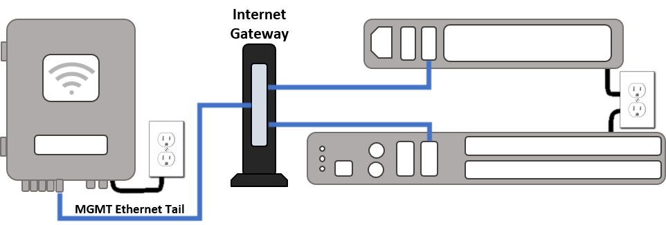
Each ReadyLinks device comes with a standard Ethernet uplink (WAN) facing port. Plug this port into your Internet gateway and follow the steps below to claim and manage your device.
Login to https://ui.readylinks.io. If this is your first time, create a new account. Claim your switches. You will need your ReadyLinks mac address (found on the device) which looks like 0013xxxxxxxx. Find the network to which you plan to add your switches or create a new network. Go to the map view and place each switch on the map by clicking and dragging it to the location where you plan to mount it.
If a firewall is in place, it must allow outgoing connections on particular ports to particular IP addresses. The most current list of outbound ports and IP addresses for your particular organization can be found on the firewall rules page of the ReadyLinks website.
All switches must be assigned routable IP addresses to be managed by ReadyView. These IP addresses can be dynamically assigned via DHCP or statically assigned.
*Note: Only one VLAN interface can be assigned a gateway. By default, all devices are configured with a single vlan interface on VLAN 1 set as a DHCP client.
When using DHCP, the DHCP server should be configured to assign a static IP address for each MAC address belonging to a ReadyLinks switch. Other features of the network, such as 802.1X authentication, may rely on the property that the switches have static IP addresses.
GL-24xT-P600D# configure terminal
GL-24xT-P600D(config)# interface vlan 10
GL-24xT-P600D(vlan-interface10)# ip address dhcp
GL-24xT-P600D(vlan-interface10)# end
GL-24xT-P600D(config)# vlan 10
GL-24xT-P600D(vlan10)# switchport tagged ethernet RJ45/G1
GL-24xT-P600D(vlan10)# end
GL-24xT-P600D(config)# management mode vlan 10
GL-24xT-P600D(config)# end
GL-24xT-P600D# show vlan int
Static IPs are assigned using the local web server on each switch. The following procedure describes how to set the static IP:
GL-24xT-P600D# configure terminal
GL-24xT-P600D(config)# interface vlan 10
GL-24xT-P600D(vlan-interface10)# ip address 10.10.0.10 255.255.255.0 10.10.0.1
GL-24xT-P600D(vlan-interface10)# end
GL-24xT-P600D(config)# vlan 10
GL-24xT-P600D(vlan10)# switchport tagged ethernet RJ45/G1
GL-24xT-P600D(vlan10)# end
GL-24xT-P600D(config)# management mode vlan 10
GL-24xT-P600D(config)# end
GL-24xT-P600D# show vlan int
GL-24xT-P600D# configure terminal
GL-24xT-P600D(config)# interface vlan 1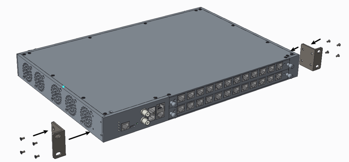
GL-24xT-P600D(vlan-interface10)# no ip addressFix the brackets on the side of the device using 8 * M3 flat head screws.
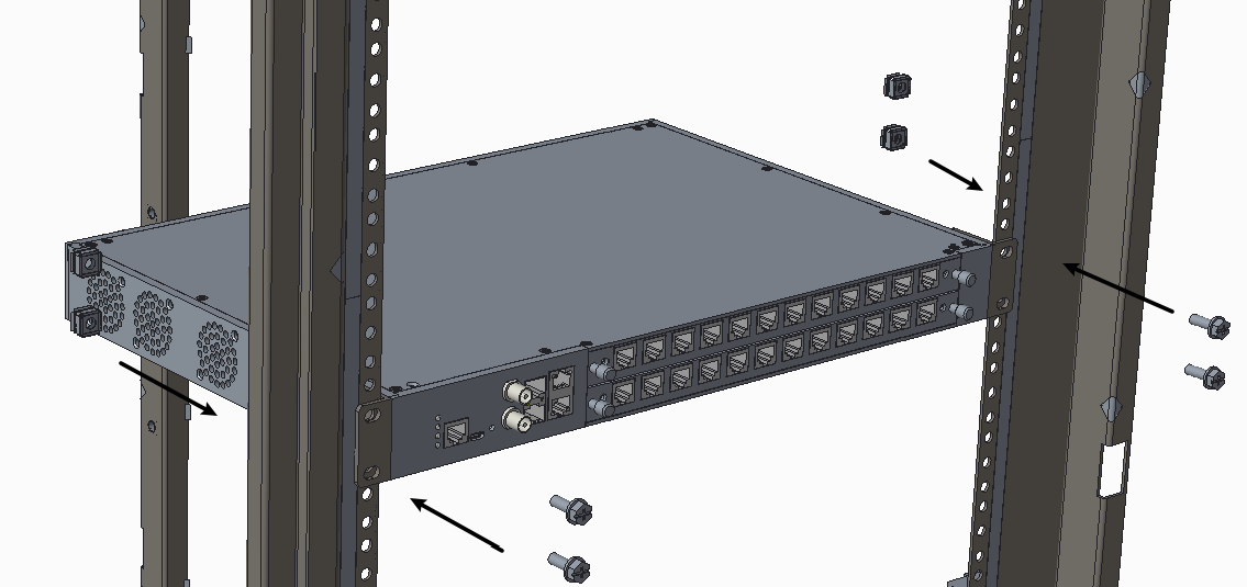
Install the GLx chassis in a 19" rack with M6 screws and nuts.
Connect the power supply to the unit.
Fix one side of the mounting plate on the wall.
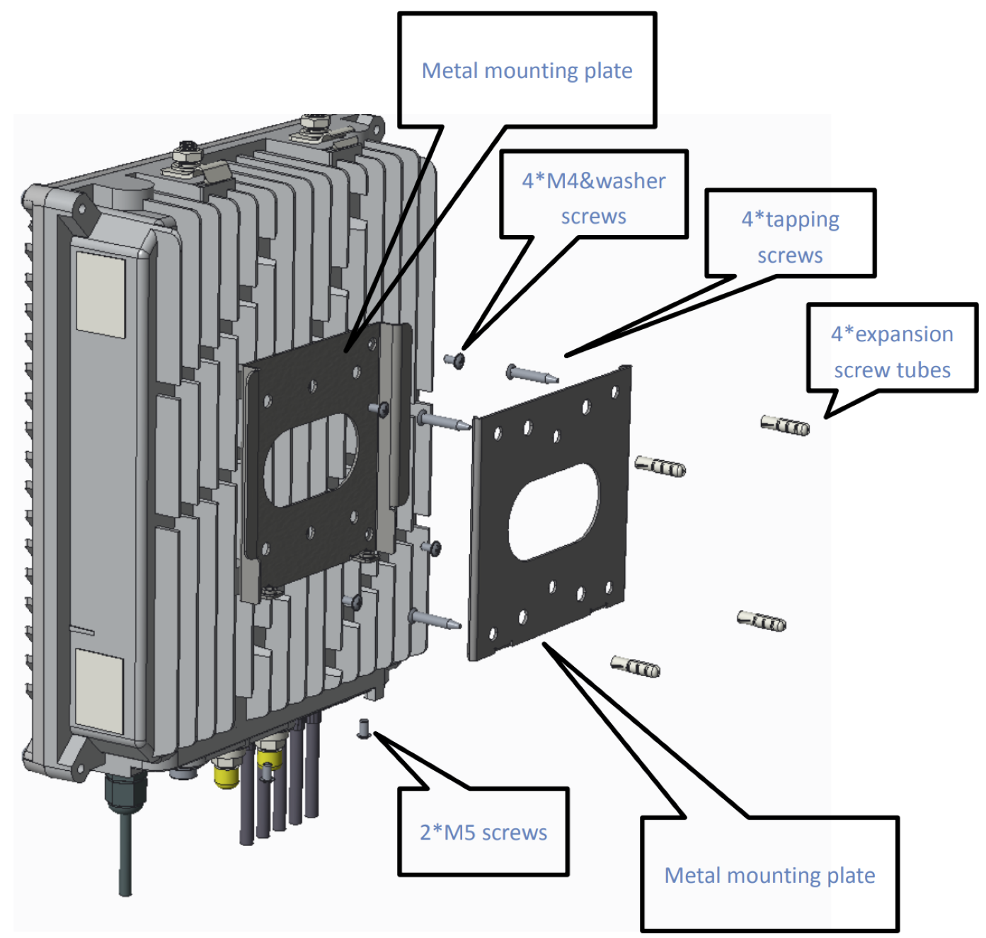
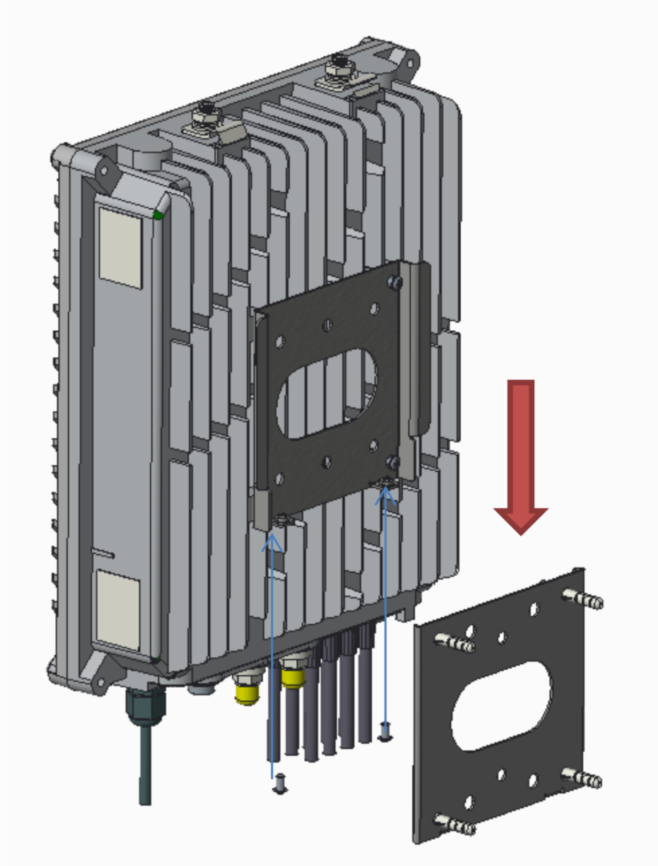
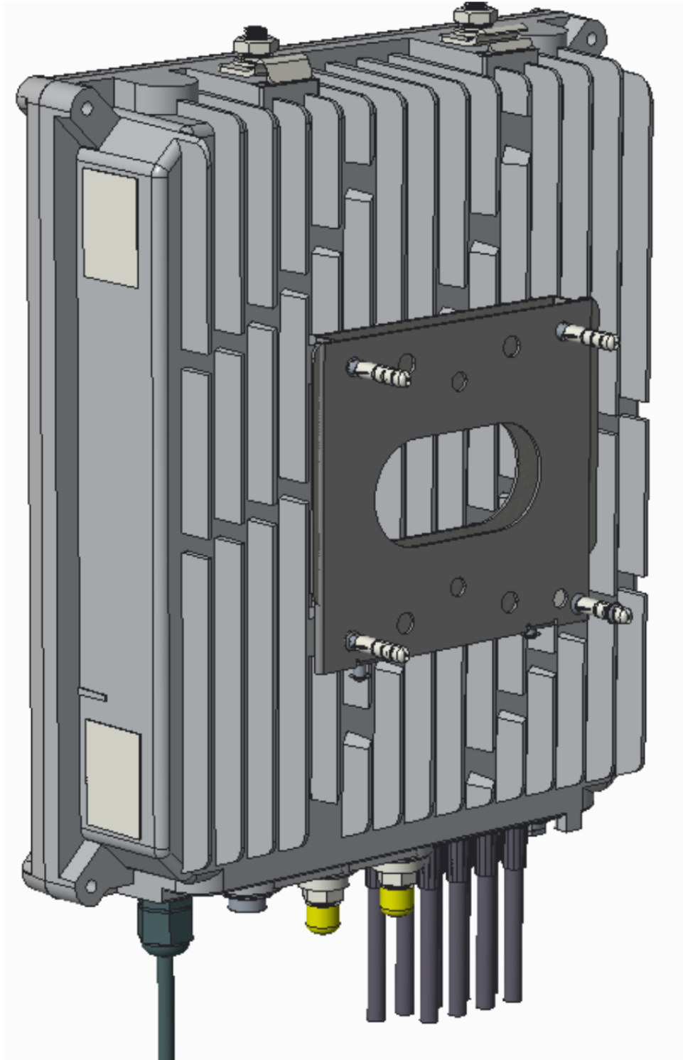
Fix the other plate on the back of the device.
Slide the device over the mounting plate and install the security screw.
Install the metal wings face down pointing toward the back of the device.
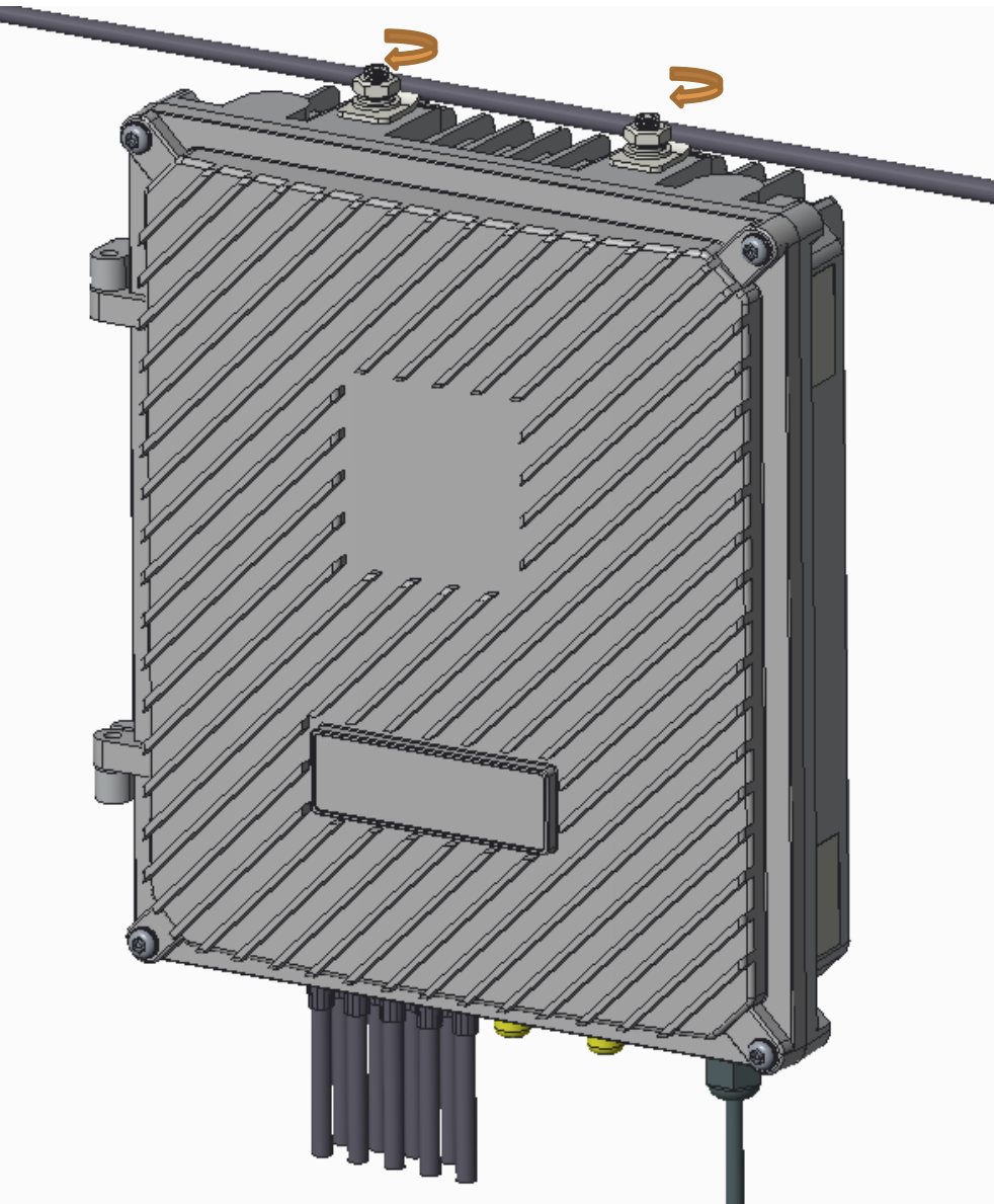
Hang the unit on the internal crossbar of the pedestal.
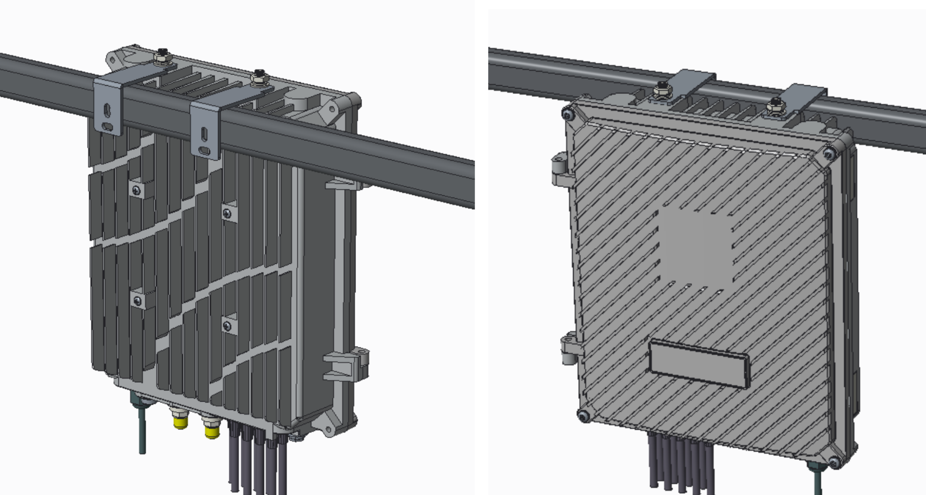
Push the wire into the gap and hang the device on the wire.
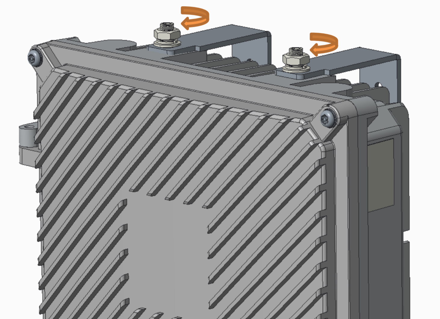
Tighten the two mounting nuts to secure the unit to the wire.
ReadyLinks coax technology can deliver Gigabit Ethernet over existing coax infrastructure and support up to 15 IPC client devices per port in coax networks with existing splitters and taps. A single GL-x chassis can deliver Gigabit Ethernet to over 360 end points through the existing coax plant.
ReadyLinks connections operate in the 4-200Mhz frequency range. If existing services such as cable TV channels are operating in this range, leverage the built-in frequency notching functionality on the ReadyLinks switch to co-exist with the services.
Follow the guidelines below when installing your ReadyLinks network over your coax infrastructure.
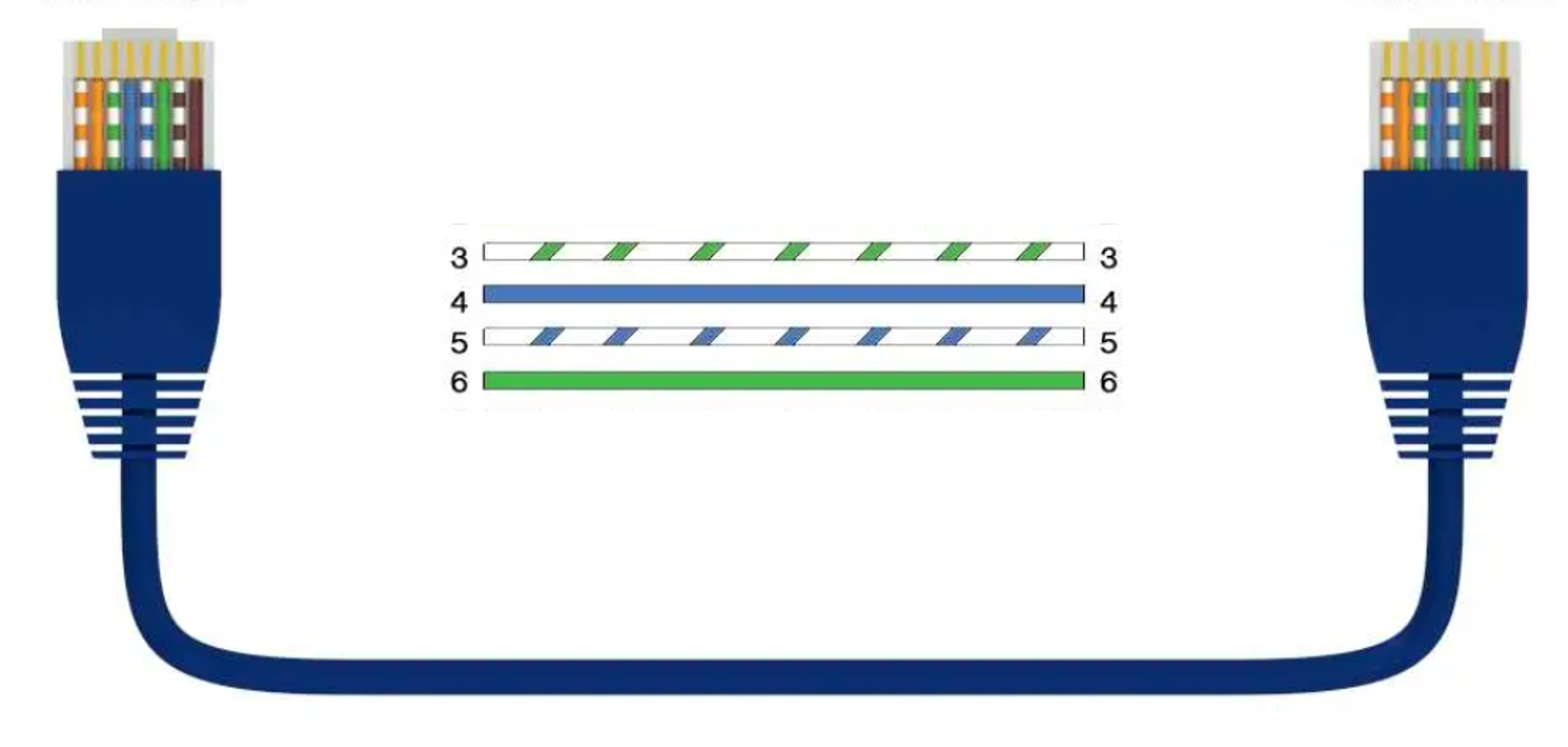
ReadyLinks twisted pair technology can deliver Gigabit Ethernet over a single pair of copper wire. Leverage two pairs to extend your reach over 1,000ft of cable.
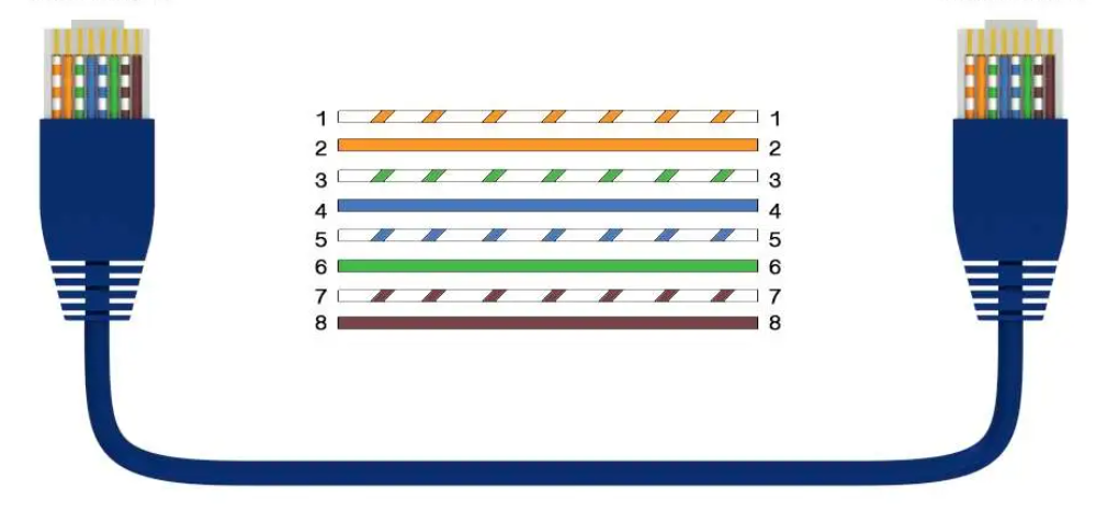
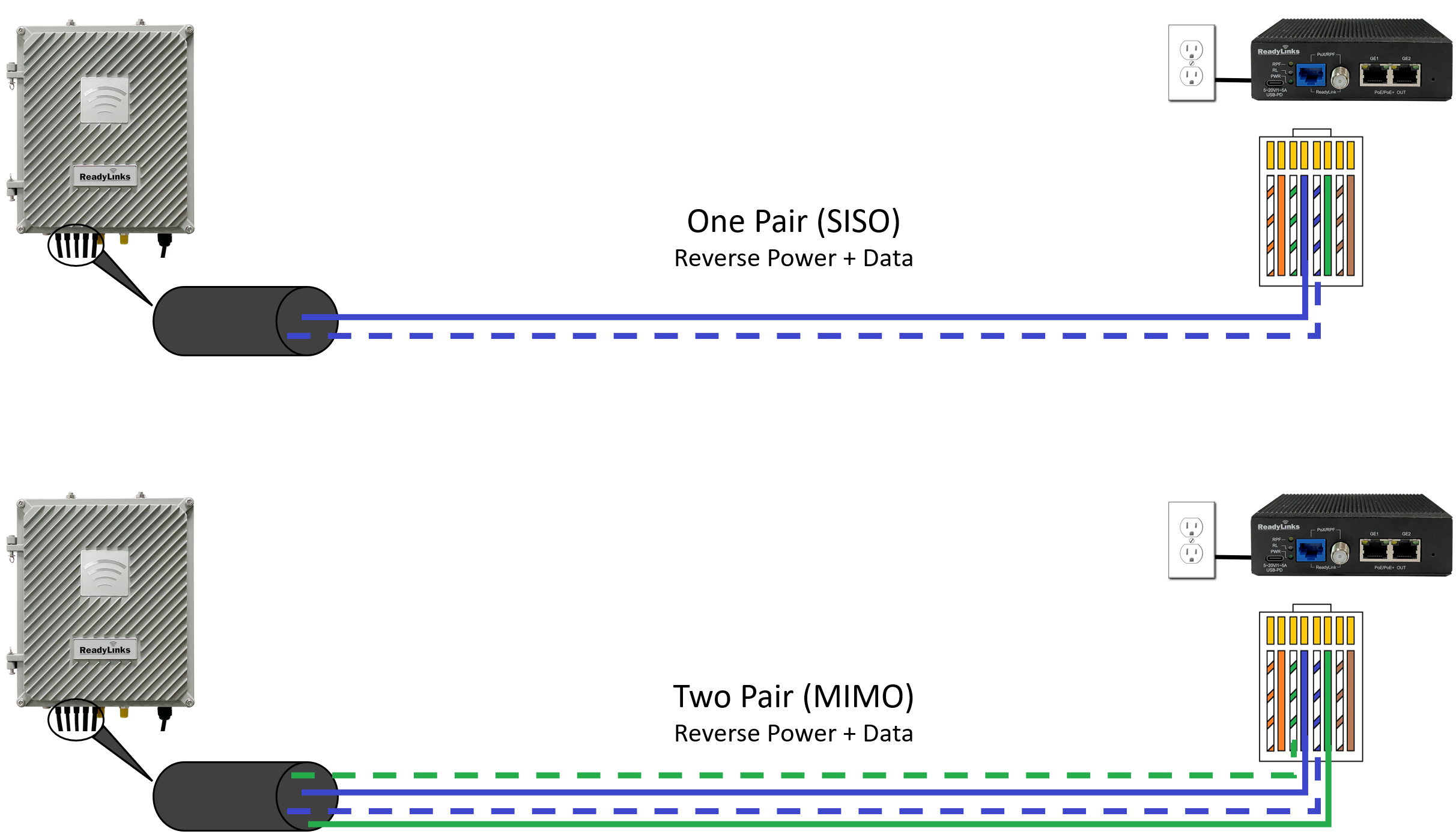
By default, ReadyLinks ports come in SISO mode, meaning we only require 1 pair to bring up the ReadyLinks connection (RJ45 pins 4 & 5).
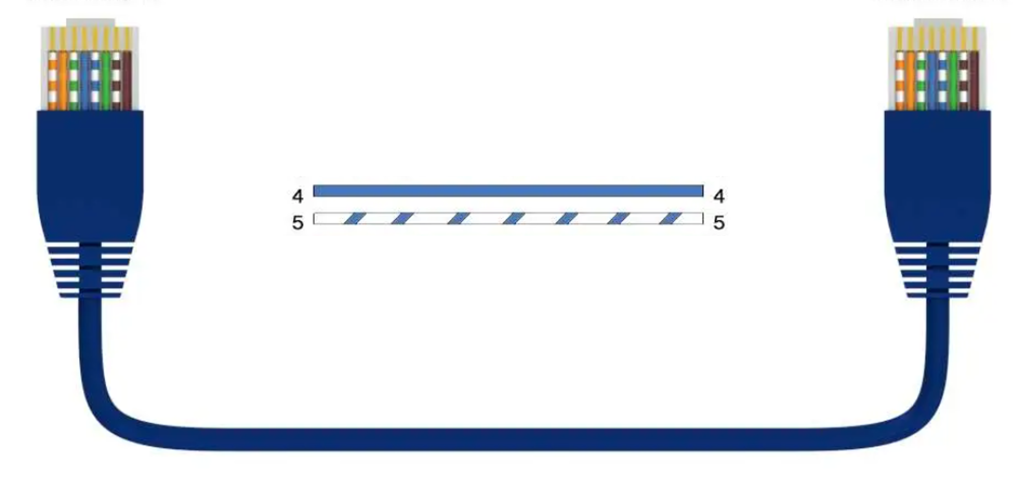
ReadyLinks ports natively include MIMO functionality in each port, meaning we can achieve higher performance at greater distances by using 2 pairs, or 4 conductors, on that port (RJ45 pins 3, 4, 5, 6). Below is the MIMO pin-out diagram. ReadyLinks recommends leveraging 2 pairs of copper, if available.
ReadyLinks RPF technology allows you to install switching equipment in locations that lack a local power source. Provide power and high-speed data over a single copper pair. Utilize a RPF enabled ReadyLinks IPC client device to backfeed power from the remote location to the switch. By default, ReadyLinks ports come in SISO mode, meaning only 1 pair is required for both the data and reverse power feed. You may adjust the default configuration to MIMO to leverage 2 copper pairs for higher performance at great distances.
The following steps can be used for troubleshooting basic connectivity issues with your switch.
ReadyLinks devices can run tests to determine the uplink status.
Verify device configurations via CLI
Note: If you have configured a static management IP address, you must also set the DNS nameservers manually on the device (dns nameserver1 8.8.8.8 nameserver2 8.8.4.4).
Check ReadyView connection status via CLI
A ReadyLink connection is capable of delivering Gigabit speeds over twisted pair or coax. To acheive maximum througput, it is important to follow some best practices.
Best practices
Refer to the twisted pair or coax cabling instructions for details on how to terminate different ReadyLink connections.
It is important to note the distance limitations for acheiving 1Gbps throughput. Speed will vary by cable type, length, and gauge, but some general guidelines for 1Gbps connections are shown below.
Througput vs Distance
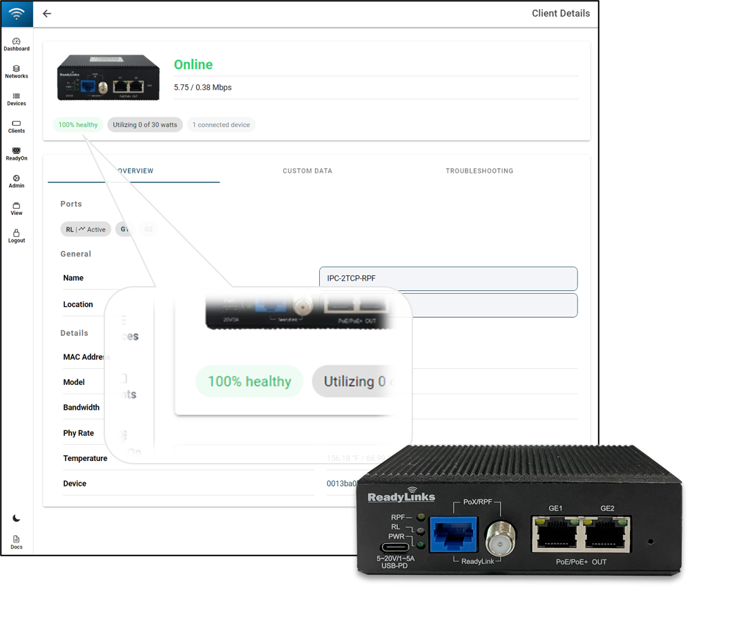
Check your connection health in the ReadyView dashboard. A low health score can indicate a poor connection, resulting in reduced throughput.
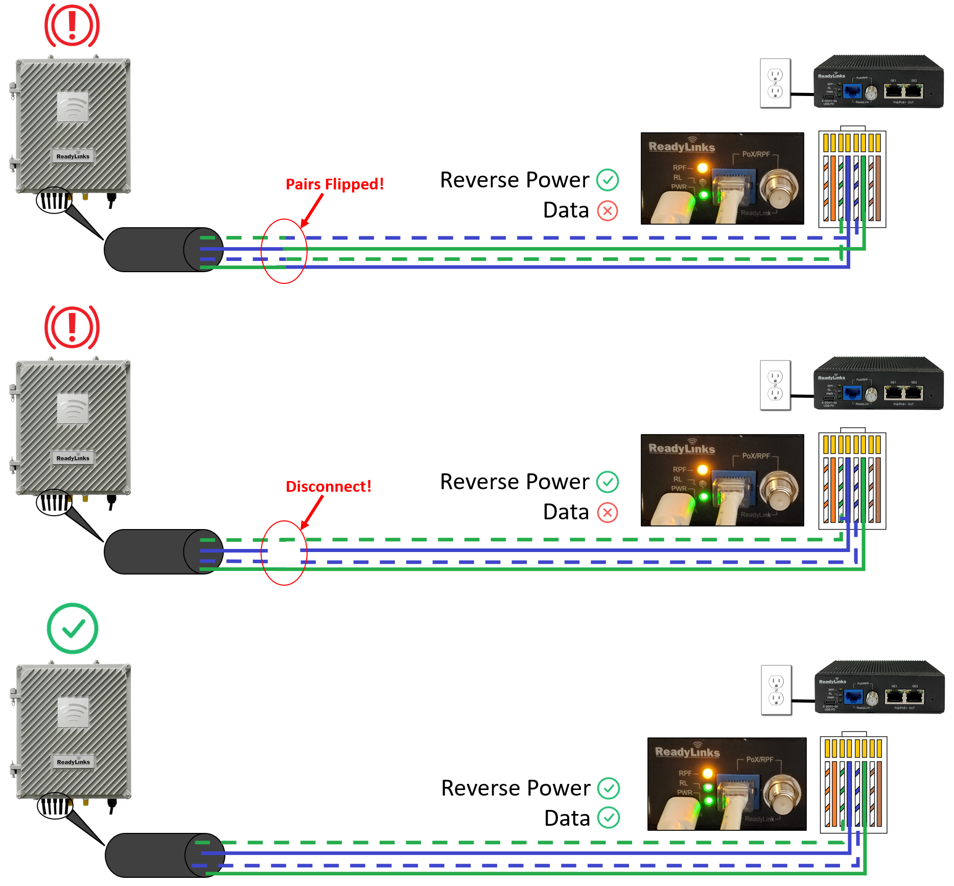
Be sure to match the center pair (pins 4 & 5) of the IPC with the correct corresponding pair on the RPF enabled switch. A mismatch in the connection may still enable the reverse power feed but the data link will remain down. Also, ensure there are no disconnects on the center pair. A stable link on the outer pair, but a disconnect on the center pair will cause the data link to fluctuate or disconnect while the RPF links stays up.
ReadyLinks Inc. products come with a default 1 Year Hardware Warranty against defects in materials and workmanship when used normally. Causes of performance issues that are beyond the reasonable control of Supplier or outlined in Non-Qualifying Outages section of this document are not included in the scope of the warranty. If your ReadyLinks device fails and the problem cannot be resolved by on-site troubleshooting, contact Partner for troubleshooting assistance. Once Partner determines that the device hardware is in a failed state, they can process an RMA and send out a replacement device. In most circumstances, the RMA will include a pre-paid shipping label so the faulty equipment can be returned.
RMAs may only be requested by Client Administrators (Read Only or Full Access to Core Services). Supplier will not process RMAs unless the Partner can verify the Client has sufficient network permissions. Non-cancellable orders are not eligible for RMA credit and are not eligible for an RMA exception.
In order to manage a ReadyLinks device through ReadyView, it must be able to communicate with the ReadyLinks cloud over a secure tunnel. This tunnel is created between ReadyLinks devices and dashboard to pass management and reporting traffic in both directions.
Because the dashboard is located on the public internet, the tunnel is always initiated outbound from the managed device. Once a connection is established, the device maintains the connection by occasionally sending packets and receiving a response. When a firewall or gateway exists in the data path between the managed device and the dashboard, certain protocols and port numbers must be permitted outbound through the firewall for the secure tunnel to function.
Confirm the device is powered on. Verify the uplink firewall rules are not blocking cloud connection traffic.
This means you have successfully claimed your device, but the device is unable to communicate with the ReadyView dashboard. Please visit this article for further troubleshooting details.
All ReadyLinks devices come with the ability to locally manage and configure the device via its web user interface or serial access port.
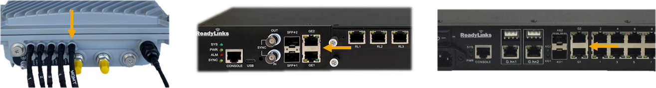
Each ReadyLinks device comes with either a standard RS-232 or a USB Type-C console port cable. Most ReadyLinks devices feature a combo USB Type-C/RJ45 console port interface, either port can be used for serial access, but note that both interfaces should not be used at the same time.
Using your serial access application of choice (i.e PuTTy), connect your PC to the ReadyLinks device and use the settings below to access the serial command line interface (CLI) of your device.
Default credentials
Serial settings
Every ReadyLinks device features a web based, Graphical User Interface (GUI), for device managment and monitoring. By default, access to this GUI is disabled.
Enable web GUI access
By default, ReadyLinks devices are provisioned as a DHCP client. Once the device is connected to a DHCP server, find the device's IP address, then open that address in a web browser.